SD card midi sample player
Section 1: Background
I'd already made the moolodeon midi melodeon a couple of years ago (see the links on the front page), and this was working fine with sound generation via a laptop. However it wasn't that portable so I wanted to find a small (ideally pocket sized) high quality sample player to use with it instead.
Unfortunately searching for a suitable product pretty much drew a blank - there were some devices capable, but they weren't small and were hundreds of pounds. So I thought it would be an interesting and challenging project to be able to build something myself.
The basic concept was to have a standard MIDI input (very easy), have a library of different sound sets that I could switch between (an SD card being the obvious cheap choice) and generate high quality (CD rate or thereabouts) sample output which would require a fairly fast CPU and a high quality DAC (harder). I also wanted it to be polyphonic as typically there is around 3-8 notes sounding simultaneously when playing a melodeon (usually bass + bass chord + treble, but you have 8 fingers at your disposal which if you're getting funky could mean 8 notes!).
Some simple sums lead me to a need to read data from the SD card at a minimum of 689kB/s ((44100 samples per second * 16 bits * 8 voices)/(8 bits per byte * 1024 bytes per kB)) which seems doable as long as there's no latency or read delays - I did also consider having a large RAM to bypass the issue of SD card performance, but at up to 10 second long samples and perhaps 64 notes per sample set it was going to need to be around 64MB which is pretty big for a microcontroller! I decided to only look into this option if the SD card direct approach didn't work out. Thankfully it did!
I had a look at a few different ideas for the choice of CPU - having used the ATMega168 in the melodeon, this wasn't going to be fast enough though the Atmel AVR UC3 (32 bit) looked quite interesting. I also considered a real DSP, but the development boards were really expensive. Having googled about a bit more, I came across the Midibox project which is based around producing MIDI control surfaces, sequencers etc using an LPC1769 processor which has an ARM Cortex M3 CPU core running at 120MHz. The project had solved the interface issues for MIDI, SD card reading (sequence data usually so small and slow) and recently hooked up a DAC (with some code for synthesizing output). Crucially though no-one had tried making a sample player - until now!
After having a chat with some people from the community, they agreed that what I was going to try should be possible and indeed there was some interest from the community for such a project. After working out the minimum hardware I would need to run the application I was pleased that the CPU development boards were really cheap! (20 euros).
So I placed an order for a board from Embedded Artists, and bought a DAC (Philips TDA1543) and some other bits (opto isolator, 3.3V regulator and misc) from Ebay, and began working on the software while the stuff was in the post...
Section 2: The Electronics
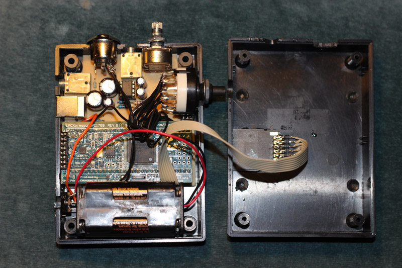
I began with a 'bare bones' setup based on the 'Minimal Circuit' described on the Midibox site which provides the USB interface, power regulation and the boot hold jumper. I then worked out (also based on the module info of the Midibox site) how to wire up the DAC (initially powered on 3.3V - but more on those problems later!), the SD card interface (the full sized SD card adapters for micro SD being a very handy and cheap way to wire up!) and the MIDI input with opto isolator, and ended up with something that looked like this (not pretty!):
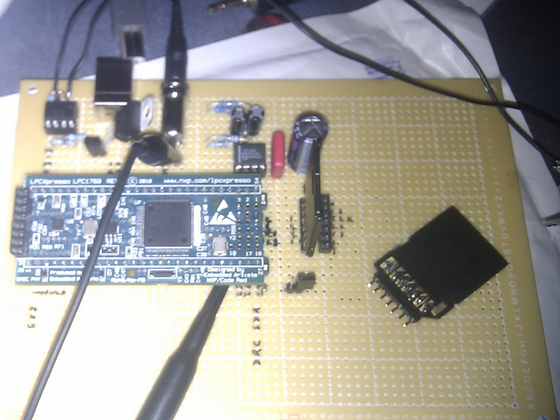
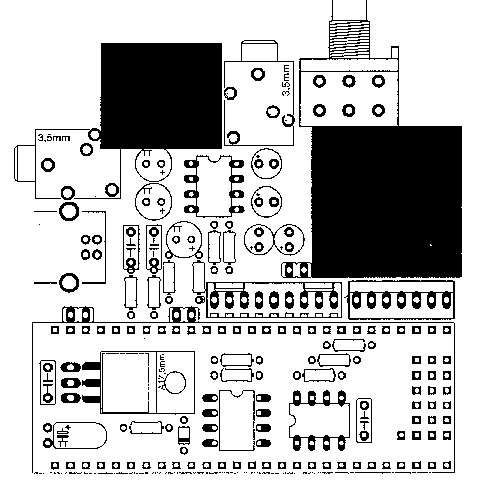
Clockwise from top left there is the opto isolator for MIDI (6N138), the USB interface (used for power and programming, also can send/receive MIDI too), the 3.3V low dropout regulator (LF33CV), the DAC (Philips TDA1543), the SD card adapter, the boot hold jumper (this prevents the normal boot-up operation into your app and allows more consistent programming environment) and finally the LPC1769 LPCExpresso board (with the JTAG programming interface removed as that's only required once to put the MIOS - Midibox OS - bootloader on, after that all programming is via the USB interface direct to the LPC1769 - I also found that with the JTAG programmer attached, sometimes the reset upon power on wouldn't work reliably, and it takes up space). My 'masterplan' aka rough schematic and parts list of the prototype is below (with full sized scan if you click the image).
 Click to enlarge
One thing that was a bit of a pain was to map the pins from the DAC, MIDI input and SD card to the pins on the LPC board. The Midibox site has some specific headers that are used to connect peripherals, but in my bare bones prototype I wanted it to be wired directly. So on the schematic you'll see some tables where I map the pins on supporting chips through to the header positions on the LPC board. The naming conventions of the pins are bit confusing too - there's PIN1 to PIN54 and PAD1 to PAD19 - the PINS being around the top and bottom of the board and the PADS being in the group on the right hand side middle! On the diagram you'll see a list of which PADS and PINS I needed to use and what they are connected to.
The LPCexpresso board when new doesn't have any pins or sockets attached, just bare through plated holes. In order to make the board removable I used some SIL headers (pins) soldered onto the LPC board, and broke apart some DIL IC sockets into single strips and populated the positions I needed to use on the strip board. It worked quite well and generally kept the board secured reliably.
One issue that came up (after getting the software up and running) was that the DAC signal to noise ratio sounded terrible, and also quite distorted. I used my oscilloscope and some code to generate sawtooth waveforms and saw this picture which is horrible! I spent ages working out what was wrong with my code (due to signed maths I was sure there was some kind of issue with the positive side) - but after giving up I tried something very simple - running the DAC from a 5V power supply instead of the 3.3V supply indicated by the Midibox guys. It immediately solved all the problems! The Philips TDA1543 datasheet says that 3.3V should be a supported supply voltage though it does recommend 5V. I'm not sure why they say supply range 3.0 and up - why anyone would put up with that distortion is beyond me!
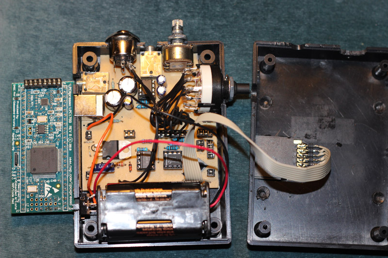
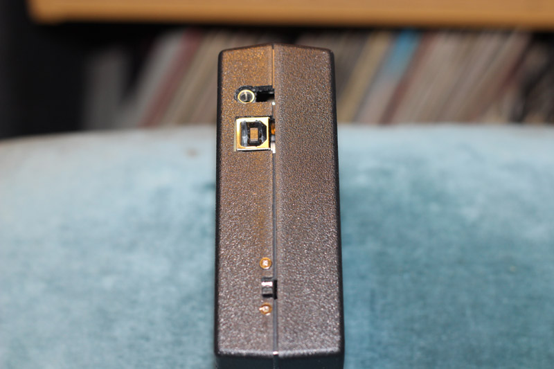
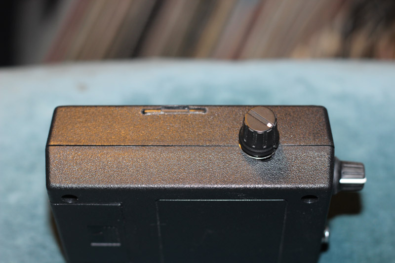
Apart from that little hiccup, the rest of the electronic side was pretty straightforward. From the prototype (which I used all during the software development) I decided to make a proper PCB, add a simple rotary switch (on the 'J10' connector in the Midibox world) to select which sample set to load, and also designed a simple (but really loud) headphone amp based around a TDA2822M 1W stereo amp chip (potentially 1W into headphones - rock on, but not too much as you'll go deaf!!). Due to trying to make the device pretty small, and after struggling to find a nice case (the one I ended up with is a bit functional and not pretty), the layout has the power regulator, the DAC and the opto isolator located under the CPU board and the SD card adapter is epoxied to the top lid with access to the microSD slot from outside (worked out really well). The components on the top half are two 3.5mm jacks (one for headphones, one for line level output), a volume knob and two blank areas where the MIDI socket and rotary switch would sit. For a power source, I went for 4 x AA batteries - after testing the current consumption it is pretty much 200mA so using some high capacity alkaline batteries perhaps 10 hours operation is expected (i've yet to flatten them to find out!). If the power switch is on, the unit runs from batteries with the headphone amp and DAC running from 6V (or whatever the batteries give out) in order to maximise the SNR. The CPU and SD card run from the 3.3V regulator. If USB is attached and the power switch is off, the unit powers from the 5V USB feed.
In terms of cost, the entire device came in pretty cheap - total around 50 UK pounds - certainly much cheaper than a commercial device.


Section 3: The Software
The Midibox community (especially Thorsten who was amazingly helpful) have done a wonderful job in creating a really easy to use environment to build devices and applications. The base platform is built around FREERTOS which is a multitasking realtime operating system. With my application a number of things happen to support the operation including: Interrupt driven receive of MIDI input data (so no need to keep polling), interrupt and DMA driven control of the sample data output to the DAC (which guarantees a consistent sample output at a set sample clock rate) via the I2S bus, functions to control of the hardware SPI interface for the SD card, and the ability to generate arbitrary operating system 'tasks' to service other regular occurences. After the initial development I ended up moving the routines to process the MIDI notes into samples (assigning voices) and also the scanning of the 'bank select' switch into their own RTOS tasks which worked really well. The voice assignment runs every 1mS, and the bank select switch is checked every 500mS - with interrupts as required to fill the DMA buffer for the DAC and to process any incoming MIDI data.
One of the key principles of operation is that the DMA buffer size was set to 512 words (with one word being 32 bits - 16 bits left and 16 bits right). At 44.1kHz sample rate this means that the buffer lasts for 5.8ms. As with everything, there's a compromise between low latency (ie delay between a note on request and audio coming out) and a bigger buffer meaning that there's more time to read sample data from the SD card. I know from experience on PC software synths that around 5ms feels pretty instantaneous, but around 10ms you start to sense the lag (and indeed by trying different arrangements in the code I proved this to myself). So 5.8ms was a good figure to reach. If the DMA fill routine fails to return within the 5.8ms, the application would crash - so it was critical to make this part of the app really efficient (later on I added a safety net that aborted further note reads if too much time was taken up reading SD card data - ie less notes on together).
So the other factor was how much data could we read from the SD card? In theory with a 30MHz clock (CPU of 120MHz/4) which was the setup from Thorsten we should be able to read one sector (which is the minimum granularity for a read) in about 0.6ms, allowing us to perhaps read 9 sectors within the 5.8ms DMA fill window. However in practice (which I measured on the oscilloscope) it was much slower than that. In the end we changed the code to clock the card at 60MHz, and with a better quality SD card (which DOES make a massive difference - genuine Sandisk all the way!) I was able to read the data much more quickly. The other big thing that helped is Thorsten wrote a routine to pre-read all the sector positions of the sample data, which avoided delays from having to look up the sector positions from the FAT table on the fly from the card - this made the app much more stable.
As time went on I added more features such as MIDI velocity support with velocity curve mapping, much of the config was put into a config file on the SD card (to avoid recompilation of the code by users), full sample bank support (with a decay envelope and sample hold for percussion samples and also fully configurable sample layering and zoning), MIDI program change for bank select etc. I was also able to reliably have full 8 voice polyphony - woohoo!!
My project page at Midibox is at This link. The code is stored on the svn repository at This Link
The end result
I'm really pleased with the end result - it sounds great, works reliably and was a really interesting project to do. Heres an example of the audio from it
Here's someone who's made a clone of the project as a loop/percussion player - which looks way cooler than mine!!
And finally, a link to the forum article about the project here
Home